Model LV350 IPEdition EN · 09 / 2026 · V1 · FW 1.5 Document No. LV350IP-EN-01
IP65 LED Moving Head · Beam Spot Wash
LV350 IP
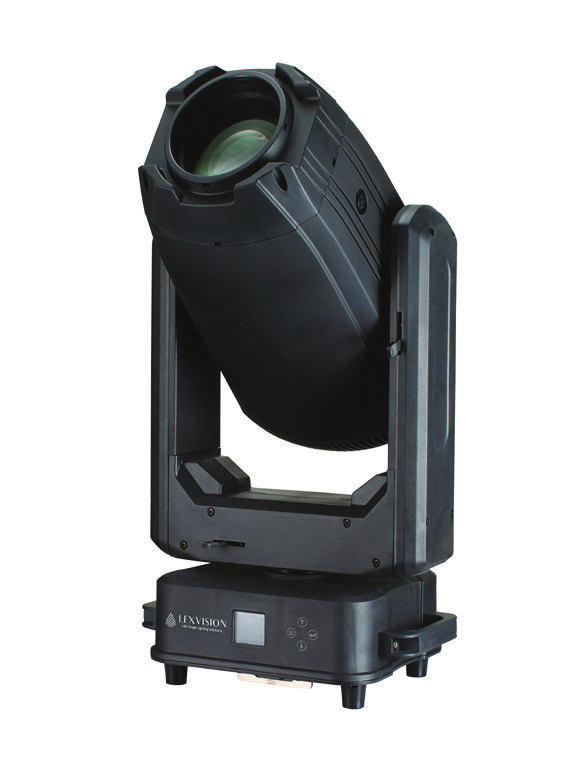
350 W LED hybrid moving head with CMY + CTO, two rotating gobo wheels, two prisms, frost and motorised zoom 3° – 38° — weatherproof to IP65
Operating manual. Please read in full before first use and keep for future reference.
Light source
350 Wwhite LED · 8,000 K
Zoom
3° – 38°motorised · focus
DMX
27 / 32channels · RDM · W-DMX opt.
IP rating
IP65indoor & outdoor
Lexvision LV350 IPForeword · About this document
Foreword
00Welcome
Thank you for choosing the Lexvision LV350 IP — a weatherproof hybrid moving head with a 350 W LED, CMY colour mixing, two rotating gobo wheels, two prisms, frost and motorised zoom / focus.
This document describes set-up, operation, care and troubleshooting of the fixture. Read the manual — in particular the chapter Safety Instructions — in full before first use and keep it with the fixture. If the fixture is passed on to third parties, the manual must be included. Damage caused by disregarding this manual is not covered by the warranty.
0.1Symbols used
WarningMarks situations in which persons may be injured or the fixture may be damaged. Always observe these instructions.
NoteMarks useful additional information, tips or explanations that aid understanding.
Danger — voltageMarks situations involving danger to life from electric current. Work on live parts is reserved for qualified personnel only.
0.2Intended use
The LV350 IP is a professional IP65-rated lighting fixture for stages, events and installations indoors and outdoors. Installation and operation by qualified personnel only. The fixture must not be connected to a dimmer pack and must not be operated by children.
0.3Package contents
1 × Lexvision LV350 IP
2 × Omega bracket
1 × Safety cable
1 × Signal cable · 1 × Power cable
1 × Operating manual
Lexvision LV350 IPContents · Overview
Table of Contents
—Overview
01Safety Instructions04
1.1General safety04
1.2Installation & mounting positions05
02Technical Specifications06
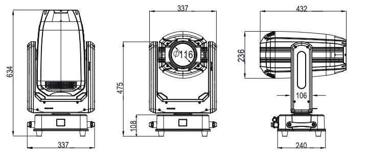
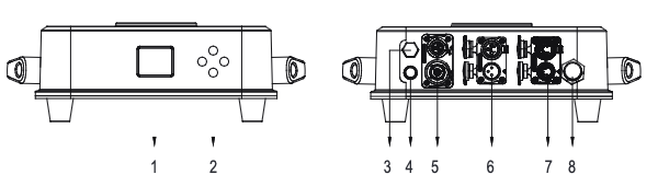
2.1Dimensions & overview07
2.2Photometrics · colour wheels · gobo wheels08
03Connecting Power & Data09
04Menu Map10
05DMX Channels (27 / 32 CH)12
06Troubleshooting15
07Cleaning & Maintenance16
—CE Declaration of Conformity16
Lexvision LV350 IP01 · Safety Instructions
Chapter 01
01Safety Instructions
Read this chapter in full before first use. Unpack the fixture and check it carefully for transport damage — do not use a damaged fixture and contact your dealer immediately.
1.1General safety
Danger to life from electric currentThe yellow/green conductor must be properly earthed. Disconnect the power before servicing, cleaning, changing accessories and long periods of non-use. Do not touch any wire during operation. Make sure the mains voltage matches the rating label (AC 100 – 264 V, 50 / 60 Hz).
Never connect the fixture to a dimmer pack. Installation and operation by qualified personnel only; do not allow children to operate the fixture.
Always use a safety cable when rigging. Carry the fixture by the base only — never by the head.
Fix the fixture firmly so that it cannot vibrate or slip during operation.
Choose a well-ventilated location: at least 50 cm from adjacent surfaces, no ventilation slot blocked — otherwise the fixture will overheat.
Ambient temperature −15 °C to +45 °C. Do not operate outside this range.
Keep flammable materials away from the fixture. Minimum distance to illuminated objects: 5 m.
The power cable must not be crimped or damaged — replace damaged cables immediately. Avoid entanglement with other cables.
The housing surface may reach 65 °C — do not touch it bare-handed during operation.
Do not allow liquids, water or metal to enter the unit — if this happens, cut the mains power immediately.
Do not operate in dirty or dusty environments; clean the fixture regularly.
Avoid direct eye exposure to the light source. Replace damaged housing parts or lenses with original parts only.
Do not operate a damaged fixture and do not attempt repairs yourself — authorised service centres only.
Use the original packaging for transport; release the PAN/TILT locks before packing. Pack only after the fixture has cooled completely; stack a maximum of 2 flight cases.
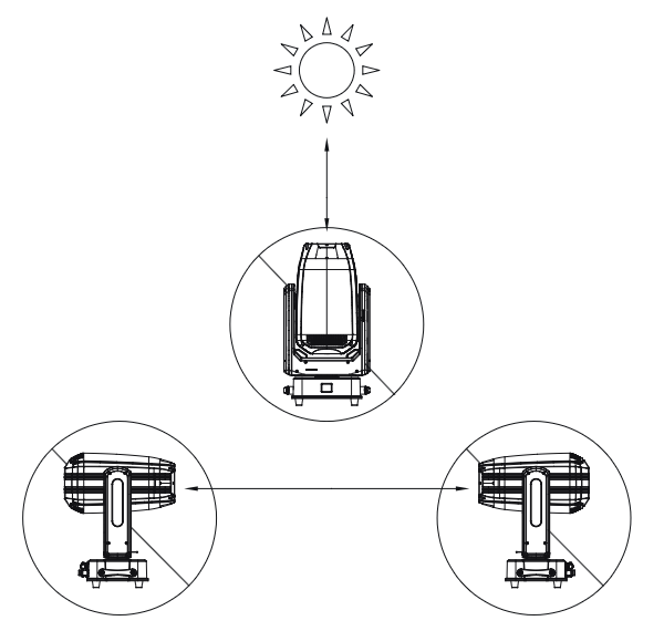
No direct sunlight on the front lensNever expose the front lens to direct sunlight or other strong light sources while unpacking, installing, operating or during extended idle times outdoors. The optics focus the light into the fixture and cause severe internal damage.
Lexvision LV350 IP01 · Safety Instructions
1.2Installation & mounting positions
The LV350 IP is rated IP65: dust cannot enter in quantities that interfere with operation, and water jets from any direction are harmless. The fixture is therefore suitable for indoor and outdoor events. Install and operate by qualified personnel only — away from walkways and seating and out of reach of unauthorised persons. Never stand directly under the fixture during installation, removal or servicing.
Risk of fallingConfirm that clamps and safety cable are intact before every installation. The truss or mounting structure must hold 6 times the fixture weight without deformation. In addition, always use a safety cable rated for at least 10 times the fixture weight in accordance with local regulations, so the fixture cannot fall if the clamp fails. Attach the safety cable to the dedicated attachment point on the base — not to the bracket.
Three mounting positions
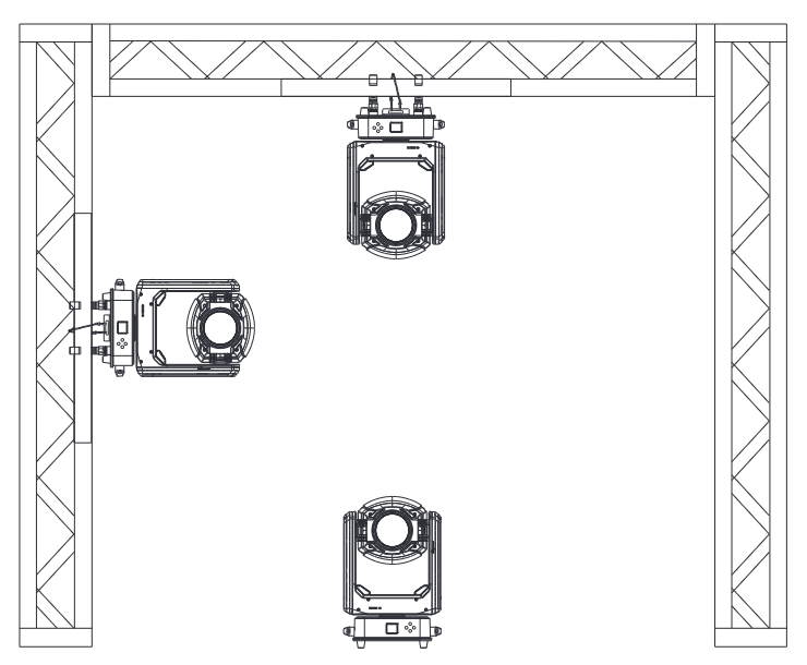
The fixture is fully operational in three positions: hanging upside-down from the truss, sideways on the truss or standing on the floor.
Installation steps
Fit the Omega bracketsInsert both Omega brackets with clamps into the attachment points on the base and lock them.
Hang the fixtureTighten the clamps on the truss; secure the fixture against slipping.
Attach the safety cableRoute the safety cable through the safety attachment point on the base and around the truss.
Route cables downwardsTo maintain the IP65 rating, all cables must point towards the ground when side-mounted so that no water accumulates around the connectors.
Fig. 1.1 — Hanging, side-mounted and standing on the truss
Lexvision LV350 IP02 · Technical Specifications
Chapter 02
02Technical Specifications
Light source & optics
Light source
1 × 350 W LED
Colour temperature
8,000 K
CRI
73 (optional 90)
Beam angle
3.4° – 33.1°
Field angle
5.5° – 38.3°
Cut-off angle
5.9° – 40.2°
Zoom / focus
motorised, 16 bit
Frost
independent frost effect
Movement
Pan / tilt
540° / 270°
Resolution
16 bit
Effects
Dimmer
0 – 100 %, 16 bit
Strobe
0 – 25 Hz
Colour mixing
CMY + CTO
Colour wheel 1 / 2
4 + open / 5 + open
Gobo wheel 1 / 2
7 + open each, rotating, shake, indexing
Prism 1 / 2
4-facet circular / 4-facet linear, index & rotate, overlapping
Navigates upwards through the menu or increases the value when in a function
DOWN ˅
Navigates downwards through the menu or decreases the value when in a function
ENTER
Enables the current displayed menu or sets the selected value into the selected function
Lexvision LV350 IP02 · Technical Specifications
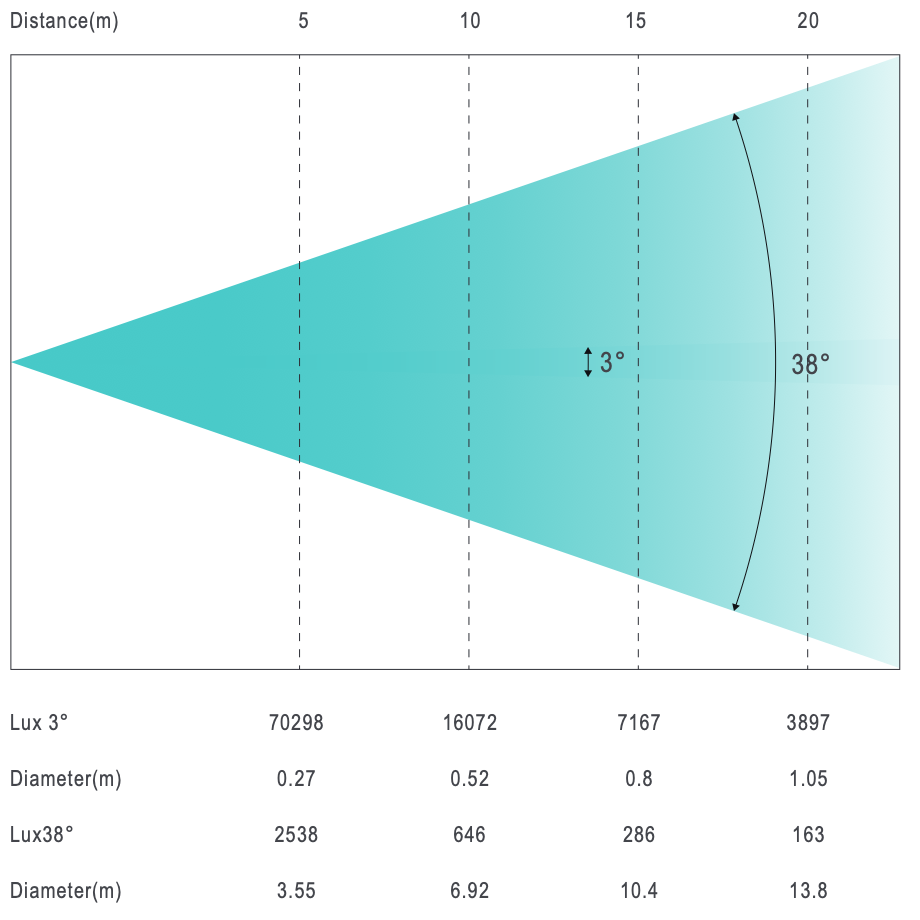
2.3Photometrics
Distance
5 m
10 m
15 m
20 m
Lux 3°
70,298
16,072
7,167
3,897
Ø (m)
0.27
0.52
0.80
1.05
Lux 38°
2,538
646
286
163
Ø (m)
3.55
6.92
10.4
13.8
2.4Colour wheels & gobo wheels
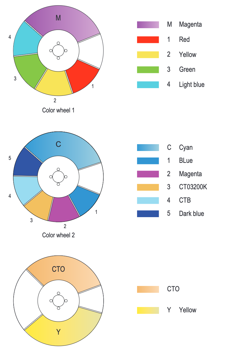
Fig. 2.3 — Colour wheel 1 (M · red · yellow · green · light blue), colour wheel 2 (C · blue · magenta · CTO 3200 K · CTB · dark blue), CTO / yellow
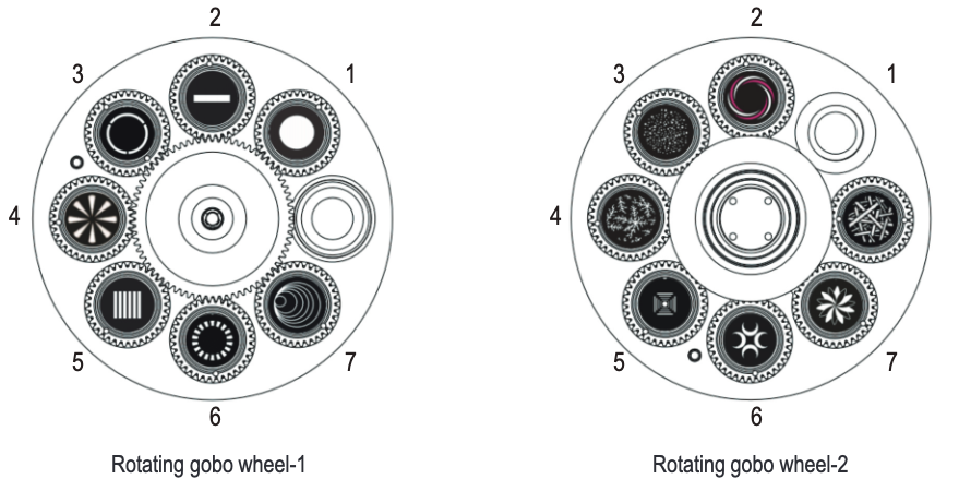
Fig. 2.4 — Rotating gobo wheels 1 and 2 (7 gobos + open each)
Gobo wheel
Gobo Ø
Image Ø
Thickness
Rotating 1
19 mm
15 mm
1.1 mm
Rotating 2
19 mm
13 mm
1.1 mm
Original gobos carry a special heat-resistant coating. Custom gobos must be made of high-temperature-resistant material or high-quality glass with identical dimensions, structure and material — differing gobos will be damaged and are excluded from the warranty. Do not use gobos with black coating on both sides (heat absorption).
Lexvision LV350 IP03 · Power & Data
Chapter 03
03Connecting Power & Data
3.1Connecting power
Release the PAN/TILT locks before connecting power.
The fixture operates on AC 100 – 260 V, 50 / 60 Hz. Maximum power consumption 542 W.
The fixture must be earthed and able to be isolated from AC power. The supply must incorporate a fuse or circuit breaker for fault protection. All wiring work must be carried out by a qualified electrician.
Colour (US)
Colour (EU)
Symbol
Conductor
Black
Brown
L
Live
White
Blue
N
Neutral
Green
Yellow / green
⏚
Ground (earth)
3.2DMX cabling
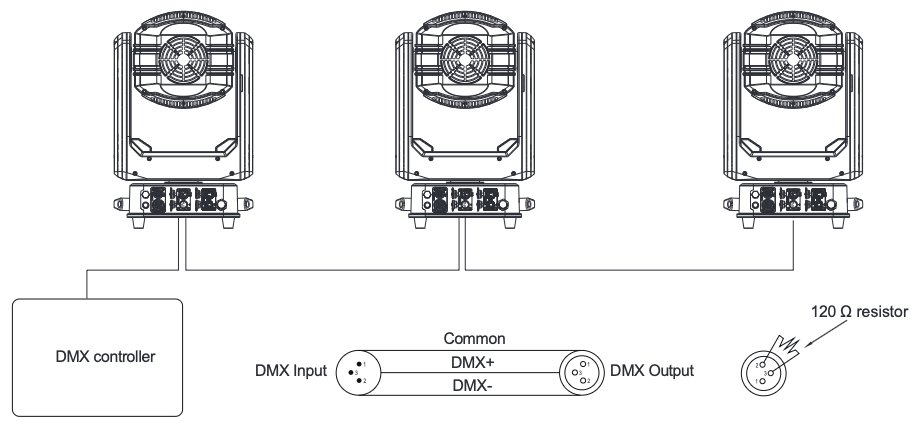
The fixture is equipped with 3-pin and 5-pin XLR sockets for DMX IN / OUT. Signal cables of up to 150 m normally work without problems; a signal amplifier is required beyond that. Use IP-rated XLR connectors between controller and fixture and between fixtures.
Building a serial DMX chain: connect the DMX output of the controller to the DMX input of the first fixture, its DMX output to the input of the next fixture, and so on. Up to 32 fixtures per DMX link. Terminate the DMX output of the last fixture with a 120 Ω DMX terminator.
Fig. 3.1 — Serial DMX chain with 120 Ω terminator
Pin 1
Common / shield
Pin 2
DMX − (data −)
Pin 3
DMX + (data +)
Pin 4 / 5
not used (5-pin)
Lexvision LV350 IP04 · Menu Map
Chapter 04
04Menu Map
Screen lock & battery operationThe screen locks automatically after a long period without operation. To unlock, press UP → DOWN → MENU → ENTER in sequence (alternatively hold MENU for 5 s, see “Screen Unlock”). Thanks to the internal battery, the menu can also be operated without mains power: hold any button for 5 seconds.
Main level
Sub-level
Options
Description
RunMode
DMX Mode
27CH · 32CH
Selects the DMX channel mode
Address
001 – 512
Selects the DMX start address
Auto Mode
Master · Alone
Master / stand-alone mode for auto programs
Manual Mode
Pan … Focus
Manually control and test all functions via the control panel (Pan, Tilt, Strobe, Dimmer, Cyan, Magenta, Yellow, CTO, Colour 1/2, Gobo 1/2 + rotation, Prism 1/2 + rotation, Frost, Zoom, Focus)
Programs
Select Program
Program 1 – 10
Select auto program 1 – 10 · Test Program
Program Edit
Step 1 – 16 = Scene
Assign scenes to steps, set scene time, test
Scene Edit
Scene 001 – 128
Edit each scene channel by channel (Pan … Focus) and its timing
Settings
Pan Reverse
Yes · No
Reversed / normal pan
Tilt Reverse
Yes · No
Reversed / normal tilt
Screen Reverse
Up · Down · Auto
Display orientation
Auto Reposition
On · Off
Automatic position correction
Pan Angle
540 · 360 · 180
Pan range
Tilt Angle
Full · 180 · 90
Tilt range
Limit Mode
Off · Up · Down
Up: pan 180° / tilt 180° · Down: pan 180° / tilt 90°
Screen Unlock
—
Press and hold MENU for 5 s to unlock the screen
DMX Loss
Hold · Off
Behaviour without DMX signal: hold last state / off
Fan Mode
Auto · Full · ECO
Fan mode
DMX Backlight
On · Off
Display stays on / off with DMX signal
Dimmer Curve
Linear · Square · Inverse square · S-Curve
Dimmer curve
Lexvision LV350 IP04 · Menu Map
4.1Menu map (continued)
Main level
Sub-level
Options
Description
Settings (cont.)
Dimmer Freq
600 · 1200 · 2000 · 4000 · 6000 · 25K
PWM frequency (Hz) — adjust for camera work
Power Down
Pan … Focus
Behaviour of the functions on power-down
Calibrate
Code 003 · Pan · Tilt · …
Fine calibration of home positions (password protected); magnetic sensitivity
W-DMX Setting
Off · On · Reset
Wireless DMX (optional) off / on / re-pair
Reset
Reset All
—
Reset all functions
Reset Scan
—
Reset pan / tilt only
Reset Other
—
Reset all functions except pan / tilt
SysInfo
Temperature
°C
Fixture temperature
Error List
—
Shows the error list
Software Version
—
Firmware version (FW 1.5)
System Update
On · Off
Enable software update
System Info
—
System information
Factory Reset
Yes · No
Restore factory default settings
4.2Setting the DMX address
Open the menuUnlock the screen, select RunMode → DMX Mode and confirm the channel mode (27CH / 32CH) with ENTER.
Select the addressOpen RunMode → Address, set the start address 001 – 512 with UP / DOWN and save with ENTER.
Light output increases linearly with the DMX value.
Square
Fine steps at low values, coarser at high values.
Inverse square
Coarser steps at low values, finer at high values.
S-Curve
Fine steps at both ends, coarser in the middle range.
Lexvision LV350 IP05 · DMX Channels
Chapter 05
05DMX Channels
The LV350 IP offers two channel modes. The 32-CH mode adds 16-bit fine channels for dimmer, gobo rotation, zoom and focus to the 27-CH mode. The two left-hand columns show the channel number in each mode.
27 CH
32 CH
Function
Value
Setting
1
1
Pan
000 – 255
0 – 100 %
2
2
Pan fine
000 – 255
Fine control, 16 bit
3
3
Tilt
000 – 255
0 – 100 %
4
4
Tilt fine
000 – 255
Fine control, 16 bit
5
5
Pan / tilt speed
000 – 255
Fast → slow
6
6
Dimmer
000 – 255
0 – 100 %
–
7
Dimmer fine
000 – 255
Fine control, 16 bit
7
8
Strobe
000 – 003
Off
004 – 007
On
008 – 076
Synchronised strobe, slow → fast
077 – 145
Pulse strobe, slow → fast
146 – 215
Random strobe, slow → fast
216 – 255
On
8
9
Colour wheel 1
000
Open
001 – 053
White → colour 1 (27)
054 – 074
Colour 1
075 – 115
Colour 1 → colour 2 (77)
116 – 136
Colour 2
137 – 175
Colour 2 → colour 3 (127)
176 – 196
Colour 3
197 – 239
Colour 3 → colour 4 (178)
240 – 255
Colour 4
9
10
Colour wheel 2
000
Open
001 – 044
White → colour 1 (28)
045 – 059
Colour 1
060 – 096
Colour 1 → colour 2 (91)
097 – 110
Colour 2
111 – 146
Colour 2 → colour 3 (156)
147 – 160
Colour 3
161 – 197
Colour 3 → colour 4 (216)
198 – 211
Colour 4
212 – 248
Colour 4 → colour 5 (228)
249 – 255
Colour 5
10
11
Cyan
000 – 255
0 – 100 %
11
12
Magenta
000 – 255
0 – 100 %
12
13
Yellow
000 – 255
0 – 100 %
13
14
CTO
000 – 255
0 – 100 %
Lexvision LV350 IP05 · DMX Channels
5.2Gobo wheels
27 CH
32 CH
Function
Value
Setting
14
15
Gobo wheel 1 (rotating)
000 – 007
Open
008 – 015
Gobo 1
016 – 023
Gobo 2
024 – 031
Gobo 3
032 – 039
Gobo 4
040 – 047
Gobo 5
048 – 055
Gobo 6
056 – 063
Gobo 7
064 – 071
Gobo 7 shake
072 – 079
Gobo 6 shake
080 – 087
Gobo 5 shake
088 – 095
Gobo 4 shake
096 – 103
Gobo 3 shake
104 – 111
Gobo 2 shake
112 – 119
Gobo 1 shake
120 – 127
Stop
128 – 187
Wheel rotation CCW, fast → slow
188 – 195
Stop
196 – 255
Wheel rotation CW, slow → fast
15
16
Gobo 1 rotation
000 – 127
Gobo index (position)
128 – 187
Gobo rotation CCW, fast → slow
188 – 195
Stop
196 – 247
Gobo rotation CW, slow → fast
248 – 255
Stop
–
17
Gobo 1 rotation fine
000 – 255
Fine control, 16 bit
16
18
Gobo wheel 2 (rotating)
000 – 007
Open
008 – 063
Gobo 1 – 7 (8 steps each, as gobo wheel 1)
064 – 127
Gobo 7 – 1 shake (8 steps each) · 120 – 127 stop
128 – 255
Wheel rotation CCW fast → slow · 188 – 195 stop · CW slow → fast
This guide contains solutions that can be carried out by an ordinary person. The fixture contains no user-serviceable parts — do not disassemble or service it unless qualified.
Problem
Potential cause
Solution
The fixture does not respond at all
No power
Check the power connection and that all cables are plugged in
Fuse damaged
Replace the fuse
Internal wiring in poor contact
Disconnect the fixture and contact your dealer
The fixture does not respond to DMX / is out of control
DMX cable disconnected
Check the DMX connections and cables
Incorrect DMX address or mode
Correct the address settings and retry
Main control board damaged
Contact your dealer
No light / LED cuts out suddenly
Fixture too hot
Power off and let it cool down; check ventilation
LED damaged
Contact your dealer
Main control board damaged
Contact your dealer
The fixture responds erratically to DMX
Connections defective
Examine connections and cables; replace damaged cables
Incorrect addressing
Check the address settings
One fixture in the chain disturbs data transmission
Bypass one fixture at a time until normal operation is restored
Colour inconsistency
Dust or spots on the colour filter
Clean the filter
Colour filter loose or damaged
Inspect / have it replaced
Gobo pattern not sharp
Dust or spots on the optical lens
Clean the lens
Optical lens damaged
Contact your dealer
Efficacy drop-off
Dirty optics / ageing
Clean; contact your dealer if necessary
Reset error (pan, tilt … prism)
Magnet lost or damaged / Hall element damaged
Examine the position / have it replaced
Obstacles in the operation zone
Make sure the operation zone is clear
Internal wiring in poor contact
Have the wiring checked
Motor or encoder damaged
Inspect / have it replaced
Repairs by qualified personnel onlyNever attempt to open or repair the fixture yourself. Repairs carried out by unqualified persons can lead to damage or malfunction and void the warranty.
Lexvision LV350 IP07 · Cleaning & Maintenance
Chapter 07
07Cleaning & Maintenance
Disconnect the power before opening the fixtureRegular cleaning and maintenance are essential for optimal performance. The operational lifespan depends largely on the operating environment and proper handling.
Important notes
All maintenance and servicing not explicitly covered in this manual must be performed by certified service technicians only.
Accumulation of dust, dirt, smoke particles or liquid deposits significantly reduces light output and heat dissipation.
Cleaning frequency varies substantially with operating conditions; no fixed interval can be specified.
Environments requiring frequent cleaning
Use of fog or haze machines
High airflow rates (e.g. near HVAC vents)
Airborne dust (stage effects, construction materials, outdoor environments)
Cleaning instructions
Clean, dry, well litWork in a clean, dry and well-lit area only.
Clean the opticsGently wipe with a soft, lint-free cloth lightly dampened with water or a mild cleaning solution.
No abrasivesNever use abrasive liquids or hard objects — optical surfaces are fragile and scratch-prone.
Let it dryAllow all parts to dry completely before powering on again.
Appendix
—EU Declaration of Conformity
The manufacturer declares under its sole responsibility that the Lexvision LV350 IP complies with the relevant EU harmonisation legislation (LVD 2014/35/EU, EMC 2014/30/EU, RoHS 2011/65/EU). The signed EU Declaration of Conformity is available as a separate document and can be requested from Lexvision GmbH, Waldweg 26, 54636 Sefferweich, Germany, by email to verkauf@lexvision.de or by phone on +49 (0) 651 14567727.
Lexvision LV350 IP · Operating Manual · Edition EN 09/2026 · V1 · Document No. LV350IP-EN-01 · Subject to technical changes and errors.